Exercices: Redressement Contrôlé Monophasé Simple Alternance
Telechargé par
Abdoulaye Sissoko

electroussafi.ueuo.com 1/4
N. ROUSSAFI electroussafi.ueuo.com Réglage de phase
Redressement contrôlé monophasé simple alternance
Exercice 1
a. P = Rg I2GT = 1W
b. es = VGT + VF + RgIGT
220√2sin100πt = 0,7V + 0,6V + 10k x 10mA (t : temps d’amorçage du thyristor)
220√2sin100πt = 101,3V 100πt = Arcsin(101,3/220√2) = 0,3316 rad =0,1π
100πt = 0,3316 rad = 0,1π t = 1ms
l’angle d’amorçage du thyristor :
t
360° T
= t x 360° / T = 19°
ou = Arcsin(101,3/220√2) = 19°
c. IGTmax = 220√2 / Rg = 220√2 /104 IGTmax = 31mA
d. Emax = 220√2 – VT ≈ 220√2 (VT est négligeable) Emax = 311V
Emoy = 96,3V
Eeff = 155V
Pt = Emax2/Rc = (220V)2/120 Pt = 403W
PC = 200W

electroussafi.ueuo.com 2/4
N. ROUSSAFI electroussafi.ueuo.com Réglage de phase
Exercice 2
1. Rt = Rgmin + Rgv
pour calculer Rgmin, on court-circuite Rgv : Rt = Rgmin et Rgv = 0
Rgmin = esmax / IGTmax = 220√2 /50mA = 6,2kΩ
on choisit une valeur standard pour Rgmin : Rgmin = 6,8kΩ
2. angle d’amorçage minimum du thyristor : min
es = VGT + VF + RgminIGT 220√2sinmin = 1V + 0,6V + 6,8k x 10mA = 69,6V
min = Arcsin(70,4/220√2) min = 12°,93
3. la valeur maximale de Rgv est calculée pour max = 90° : angle d’amorçage maximum
du thyristor
esmax = VGT + VF + (Rgmin+ Rgvmax)IGT
220√2 = 1V + 0,6V + (6,8k + Rgvmax) x 10mA =69,6V + Rgvmax x 10mA
Rgvmax = (220√2 - 69,6V) / 10mA Rgvmax ≈ 24kΩ
4. = 45°
a. Rgv = (220√2sin45 - 69,6V) / 10mA = 14,96kΩ Rgv ≈ 15 kΩ
b.
Eeff = 148,3V
Pt = Emax2/Rc = (220V)2/20 Pt = 2420W
PC = 1100W

electroussafi.ueuo.com 3/4
N. ROUSSAFI electroussafi.ueuo.com Réglage de phase
Exercice 3
1. Emax = 220√2V Emax = 311V
Eeff = Emax / 2 Eeff = 155,6V
Ieff = Eeff / Rc Ieff = 7,78A
P = Eeff x Ieff / 2 = (Emax /2)2/2Rc = 2202 / 40 P = 1210W
2. = 60° : on a redresseur contrôlé simple alternance
Eeff = 139,5V
Ieff = Eeff / Rc Ieff = 6,97A
Imoy = Emoy /Rc et Emoy = (Emax /2π) (1 + cos) Imoy = (Emax /2πRc) (1 + cos)
Imoy = (2202/40π) (1 + cos60°) Imoy = 3,7A
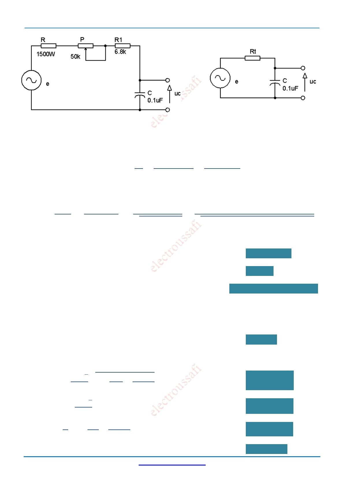
Exercice 4
1. Le thyristor devient passant lorsque la tension aux bornes du condensateur C :
uc = VD + VGT = 0,6V + 0,7V uc = 1,3V
Le thyristor est bloqué pendant l’alternance négative et tant que uc < 1,3V.
2. La diode protège la gâchette contre les tensions négatives.
3. Avant l’amorçage du thyristor (thyristor = interrupteur ouvert et diode = interrupteur
ouvert), le montage se comporte comme un circuit RC en alternatif, et le schéma du
montage devient :
electroussafi.ueuo.com 4/4
N. ROUSSAFI electroussafi.ueuo.com Réglage de phase
≡
Rt = P + R1 + R = P + R1 (R est négligeable) Rt = 26,8k
4. La fonction du transfert du circuit RC est :
5. e = Emax sin100πt Emax = 220√2V uc = Ucmax sin(ωt + φ)
ω
Uceff = |Av| x Eeff Uceff√2 = |Av| x Eeff √2
Ucmax = 220√2V |Av| Ucmax = 238V
φ = -ArctgRtCω = - Arctg φ = -40°
uc = Ucmax sin (ωt + φ) uc = 238Vsin(100πt – 40°)
6. Angle d’amorçage : le thyristor devient passant lorsque uc = 1,3V.
uc = 238V sin ( + φ) = 1,3V + φ = Arcsin1,3/238 = 0°,3
= 0°,3 - φ = 0°,3 – (-40°) = 40°,3
7. On a un redresseur contrôlé simple alternance.
Eeff = 150,27V
Emoy = 87,28V
avec Pt = 1500W Pc = 699,84W
8. Ieff = Eeff / 13Ω Ieff = 11,55A
1
/
4
100%