
1
Chiller Plant Design
Introduction
Using chilled water to cool a building or process is efficient and flexible. A two-inch Schedule
40 pipe of chilled water can supply as much comfort cooling as 42" diameter round air duct. The
use of chillers allows the design engineer to produce chilled water in a central building location
or even on the roof and distribute the water economically and without the use of large duct
shafts. Chilled water also provides accurate temperature control that is especially useful for
variable air volume (VAV) applications.
The purpose of this manual is to discuss various piping and control strategies commonly used
with chilled water systems including variable flow pumping systems.
Using This Guide
This Guide initially discusses the components used in a chilled water
system. It then reviews various chiller plant designs explaining their
operation, strengths and weaknesses. Where appropriate, sequence of
operations are provided. Each project is unique so these sequences are
just guidelines.
In addition, many sections reference ASHRAE Standard 90.1-
2001.
The ASHRAE section numbers are provided in parentheses to direct the
reader. The sections referenced in this Guide are by no means complete.
It is recommended that the reader have access
to a copy of Standard
90.1 as well as the Users Manual. The Standard and manual can be
purchased online at http://energy-models.com/WWW.ASHRAE.org.
Basic System
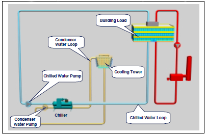
Figure 1 shows a basic chiller loop with a water-cooled chiller. The system consists of a chiller,
cooling tower, building cooling load, chilled water and condensing water pumps and piping. This
section will review each of the components.
Figure 1 - Single Chiller Loop

2
Chiller Basics
The chiller can be water-cooled, air-cooled or evaporatively cooled. The compressor types
typically are reciprocating, scroll, screw or centrifugal. The evaporator can be remote from the
condensing section on air-cooled units. This has the advantage of allowing the chilled water loop
to remain inside the building envelope when using an outdoor chiller. In applications where
freezing conditions can be expected, keeping the chilled water loop inside the building avoids the
need for some form of antifreeze.
There can be multiple chillers in a chilled water plant. The details of various multiple chiller
plant designs will be discussed in future sections.
The chilled water flows through the evaporator of the chiller. The evaporator is a heat exchanger
where the chilled water gives up its sensible heat (the water temperature drops) and transfers the
heat to the refrigerant as latent energy (the refrigerant evaporates or boils).
Flow and Capacity Calculations
For air conditioning applications, the common design conditions are 44oF supply water
temperature and 2.4 gpm/ton. The temperature change in the fluid for either the condenser or the
evaporator can be described using the following formula:
Q = W × C × ΔT
Where
Q = Quantity of heat exchanged (Btu/hr)
W = flow rate of fluid (USgpm)

3
C = specific heat of fluid (Btu/lb- oF)
ΔT = temperature change of fluid (oF )
Assuming the fluid is water, the formula takes the more common form of:
Load (Btu/hr) = Flow (USgpm) × (oFin - oFoutt) × 500
Or
Load (tons) = Flow (USgpm) × (oFin - oFout)/24
Using this equation and the above design conditions, the temperature change in the evaporator is
found to be 10oF. The water temperature entering the evaporator is then 54oF.
Most air conditioning design conditions are based on 75oF and 50% relative humidity (RH) in
the occupied space. The dewpoint for air at this condition is 55.08oF. Most HVAC designs are
based on cooling the air to this dewpoint to maintain the proper RH in the space. Using a 10oF
approach at the cooling coil means the supply chilled water needs to be around 44oF or 45oF.
The designer is not tied to these typical design conditions. In fact, more energy efficient
solutions can be found by modifying the design conditions, as the project requires.
Changing the chilled water flow rate affects a specific chiller's performance. Too low a flow rate
lowers the chiller efficiency and ultimately leads to laminar flow. The minimum flow rate is
typically around 3 fps (feet per second). Too high a flow rate leads to vibration, noise and tube
erosion. The maximum flow rate is typically around 12 fps. The chilled water flow rate should be
maintained between these limits of 3 to 12 fps.
The condenser water flows through the condenser of the chiller. The condenser is also a heat
exchanger. In this case the heat absorbed from the building, plus the work of compression, leaves
the refrigerant (condensing the refrigerant) and enters the condenser water (raising its
temperature). The condenser has the same limitations to flow change as the evaporator.
Chillers and Energy Efficiency
Chillers are often the single largest electricity users in a building. A 1000 ton chiller has a motor
rated at 700 hp. Improving the chiller performance has immediate benefit to the building
operating cost. Chiller full load efficiency ratings are usually given in the form of kW/ton, COP
(Coefficient of Performance = kWcooling / kWinput) or EER (Energy Efficiency Ratio = Tons X 12/
kWinput). Full load performance is either the default ARI conditions or the designer specified
conditions. It is important to be specific about operating conditions since chiller performance
varies significantly at different operating conditions.
Chiller part load performance can be given at designer-specified conditions or the NPLV (Non-
Standard Part Load Value) can be used. The definition of NPLV is spelled out in ARI 550/590-

4
98, Test Standard for Chillers. For further information refer to McQuay Application Guide AG
31-002, Centrifugal Chiller Fundamentals.
☺
Tip: To convert from COP to kW/ton;
COP = 3.516/(kW/ton)
To calculate EER = Tons x 12/(total kW input)
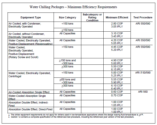
Figure 2 - ASHRAE Std 90.1 Chiller Performance Table1
Since buildings rarely operate at design load conditions (typically less than 2% of the time)
chiller part load performance is critical to good overall chiller plant performance. Chiller full and
part load efficiencies have improved significantly over the last 10 years (Chillers with NPLVs of
0.35 kW/ton are available) to the point where future chiller plant energy performance will have
to come from chiller plant design.

5
ASHRAE Standard 90.1-2001 includes mandatory requirements for minimum chiller
performance. Table 6.2.1.C of this standard covers chillers at ARI standard conditions. Tables
6.2.1H to M cover centrifugal chillers at non-standard conditions.
1 Copyright 2001, American Society Of Heating, Air-conditioning and Refrigeration Engineers
Inc., http://energy-models.com/www.ashrae.org. Reprinted by permission from ASHRAE
Standard 90.1-2001
Piping Basics
Static Pressure
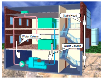
Figure 3 - Closed Loop
The piping is usually steel, copper or plastic. The chilled water piping is usually a closed loop. A
closed loop is not open to the atmosphere. Figure 3 shows a simple closed loop with the pump at
the bottom of the loop. Notice that the static pressure created by the change in elevation is equal
on both sides of the pump. In a closed loop, the pump needs only to overcome the friction loss in
the piping and components. The pump does not need to "lift" the water to the top of the loop.
When open cooling towers are used in condenser piping, the loop is an open type. Condenser
pump must overcome the friction of the system and "lift" the water from the sump to the top of
the cooling tower. Figure 4 shows an open loop. Notice the pump need only overcome the
elevation difference of the cooling tower, not the entire building.
☺
Tip: Most chillers are rated for 150 PSI water side pressure. This should be considered
carefully for buildings over 10 stories.
In high-rise applications, the static pressure can become considerable and exceed the pressure
rating of the piping and the components such as chillers. Although chillers can be built to higher
 6
7
8
9
10
11
12
13
14
15
16
17
18
19
20
21
22
23
24
25
26
27
28
29
30
31
32
33
34
35
36
37
38
39
40
41
42
43
44
45
46
47
48
49
50
51
52
53
54
55
56
57
58
59
60
61
62
63
64
65
66
67
68
69
70
71
72
6
7
8
9
10
11
12
13
14
15
16
17
18
19
20
21
22
23
24
25
26
27
28
29
30
31
32
33
34
35
36
37
38
39
40
41
42
43
44
45
46
47
48
49
50
51
52
53
54
55
56
57
58
59
60
61
62
63
64
65
66
67
68
69
70
71
72
1
/
72
100%
