Solar Pumping VFD
Goodrive100-PV Series

Goodrive100-PV Series Solar Pumping VFD Contents
i
Contents
Contents .................................................................................................................................... i
1 Safety precautions ............................................................................................................... 1
1.1 Safety definition ............................................................................................................. 1
1.2 Warning symbols ........................................................................................................... 1
1.3 Safety guidelines ........................................................................................................... 2
2 Product overview.................................................................................................................. 4
2.1 Unpacking inspection .................................................................................................... 4
2.2 Name plate .................................................................................................................... 4
2.3 Type designation key ..................................................................................................... 4
2.4 Product specifications .................................................................................................... 5
2.5 Rated specifications ...................................................................................................... 5
3 Installation guidelines .......................................................................................................... 7
3.1 Mechanical installation .................................................................................................. 7
3.2 Standard wiring .............................................................................................................. 9
4 Keypad operation procedure ............................................................................................ 14
4.1 Keypad introduction ..................................................................................................... 14
4.2 Keypad displaying ....................................................................................................... 17
4.3 Keypad operation ........................................................................................................ 18
5 Commissioning guidelines ................................................................................................ 20
5.1 Inspection before operation ......................................................................................... 20
5.2 Trial run ........................................................................................................................ 20
5.3 Parameter settings ...................................................................................................... 20
5.4 Advanced settings ....................................................................................................... 20
6 Function parameters .......................................................................................................... 22
6.1 Common function parameters for solar pumping control ............................................ 22
6.2 Parameters of special functions .................................................................................. 41
7 Fault diagnosis and solution ............................................................................................. 59
Appendix A Options and use ................................................................................................ 65
A.1 Boost module .............................................................................................................. 65
A.2 GPRS module and monitoring APP ............................................................................ 66
A.3 Cables ......................................................................................................................... 67
A.4 Reactors ...................................................................................................................... 69
A.5 Filters........................................................................................................................... 70
Appendix B Recommended solar modules ........................................................................ 71
B.1 Recommended configuration for solar pumping VFDs ............................................... 71
B.2 Recommended configuration for VFDs with the boost module ................................... 72
Appendix C Power frequency & PV switching solution .................................................... 73
C.1 Solution introduction ................................................................................................... 73
C.2 IP54 protection-level VFDs ......................................................................................... 77
C.3 Wiring terminals .......................................................................................................... 78
C.4 Parameter setting method ........................................................................................... 79
Appendix D Dimension drawings ........................................................................................ 80
D.1 External keypad structure ........................................................................................... 80
D.2 Dimensions of 0.4-2.2kW models ............................................................................... 81
D.3 Dimensions of 1.5-200kW models .............................................................................. 83
Appendix E Further information .......................................................................................... 86
E.1 Product and service inquiries ...................................................................................... 86
Goodrive100-PV Series Solar Pumping VFD Safety precautions
1
1 Safety precautions
Please read this manual carefully and follow all safety precautions before moving, installing,
operating and servicing the variable-frequency drive (VFD). If ignored, physical injury or death
may occur, or damage may occur to the devices.
If any physical injury or death or damage to the devices occurs for ignoring to the safety
precautions in the manual, our company will not be responsible for any damages and we are
not legally bound in any manner.
1.1 Safety definition
Danger:
Serious physical injury or even death may occur if not follow
relevant requirements
Warning:
Physical injury or damage to the devices may occur if not follow
relevant requirements
Note:
Physical hurt may occur if not follow relevant requirements
Qualified
electricians:
People working on the device should take part in professional
electrical and safety training, receive the certification and be
familiar with all steps and requirements of installing,
commissioning, operating and maintaining the device to avoid
any emergency.
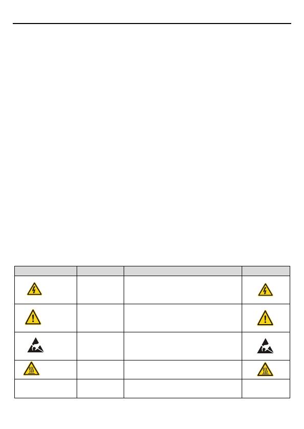
1.2 Warning symbols
Warnings caution you about conditions which can result in serious injury or death and/or
damage to the equipment, and advice on how to avoid the danger. Following warning symbols
are used in this manual:
Symbols
Name
Instruction
Abbreviation
Danger
Danger
Serious physical injury or even
death may occur if not follow the
relative requirements
Warning
Warning
Physical injury or damage to the
devices may occur if not follow the
relative requirements
Do not
Electrostatic
discharge
Damage to the PCBA board may
occur if not follow the relative
requirements
Hot sides
Hot sides
Sides of the device may become
hot. Do not touch.
Note
Note
Physical hurt may occur if not follow
the relative requirements
Note
Goodrive100-PV Series Solar Pumping VFD Safety precautions
2
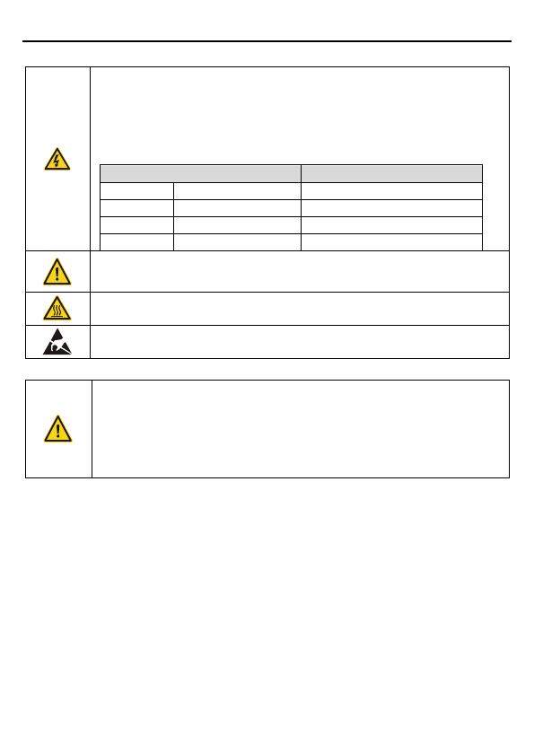
1.3 Safety guidelines
Only qualified electricians are allowed to operate on the VFD.
Do not carry out any wiring and inspection or changing components when
the power supply is applied. Ensure all input power supply is disconnected
before wiring and checking and always wait for at least the time designated
on the VFD or until the DC bus voltage is less than 36V. Below is the table
of the waiting time:
VFD model
Minimum waiting time
1PH 220V
0.4kW-2.2kW
5 minutes
3PH 220V
1.5kW-7.5kW
5 minutes
3PH 380V
0.75kW-110kW
5 minutes
3PH 380V
132kW-200kW
15 minutes
Do not refit the VFD unauthorized; otherwise fire, electric shock or other
injury may occur.
The base of the radiator may become hot during running. Do not touch to
avoid hurt.
The electrical parts and components inside the VFD are electrostatic. Take
measurements to avoid electrostatic discharge during relevant operation.
1.3.1 Delivery and installation
Please install the VFD on fire-retardant material and keep the VFD away
from combustible materials.
Do not operate on the VFD if there is any damage or components loss to
the VFD.
Do not touch the VFD with wet items or body, otherwise electric shock may
occur.
Note:
Select appropriate moving and installing tools to ensure a safe and normal running of the
VFD and avoid physical injury or death. For physical safety, the erector should take some
mechanical protective measurements, such as wearing safety shoes and working uniforms.
Do not carry the VFD by its cover. The cover may fall off.
Ensure to avoid physical shock or vibration during delivery and installation.
Install away from children and other public places.
The VFD cannot meet the requirements of low voltage protection in IEC61800-5-1 if the
altitude of installation site is above 2000m.
The leakage current of the VFD may be above 3.5mA during operation. Ground with proper
techniques and ensure the grounding resistor is less than 10Ω. The conductivity of PE
grounding conductor is the same as that of the phase conductor (with the same cross
sectional area).
Goodrive100-PV Series Solar Pumping VFD Safety precautions
3
(+) and (-) are DC power supply input terminals. R, S and T (L,N) are AC power supply
input terminals. U, V and W are output terminals. Please connect the input power cables
and motor cables with proper techniques; otherwise the damage to the VFD may occur.
1.3.2 Commissioning and running
Disconnect all power supplies applied to the VFD before the terminal
wiring and wait for at least the designated time after disconnecting the
power supply.
High voltage is present inside the VFD during running. Do not carry out
any operation except for the keypad setting.
The VFD cannot be used as “Emergency-stop device”.
If the VFD is used to break the motor suddenly, a mechanical braking
device should be provided.
Note:
Do not switch on or off the input power supply of the VFD frequently.
For VFDs that have been stored for a long time, check and fix the capacitance and try to
run it again before utilization.
Cover the front board before running, otherwise electric shock may occur.
1.3.3 Maintenance and replacement of components
Only qualified electricians are allowed to perform the maintenance,
inspection, and components replacement of the VFD.
Disconnect all power supplies to the VFD before the terminal wiring. Wait
for at least the time designated on the VFD after disconnection.
Take measures to avoid screws, cables and other conductive materials to
fall into the VFD during maintenance and component replacement.
Note:
Please select proper torque to tighten screws.
Keep the VFD, parts and components away from combustible materials during
maintenance and component replacement.
Do not carry out any isolation voltage-endurance test on the VFD and do not measure the
control circuit of the VFD by megameter.
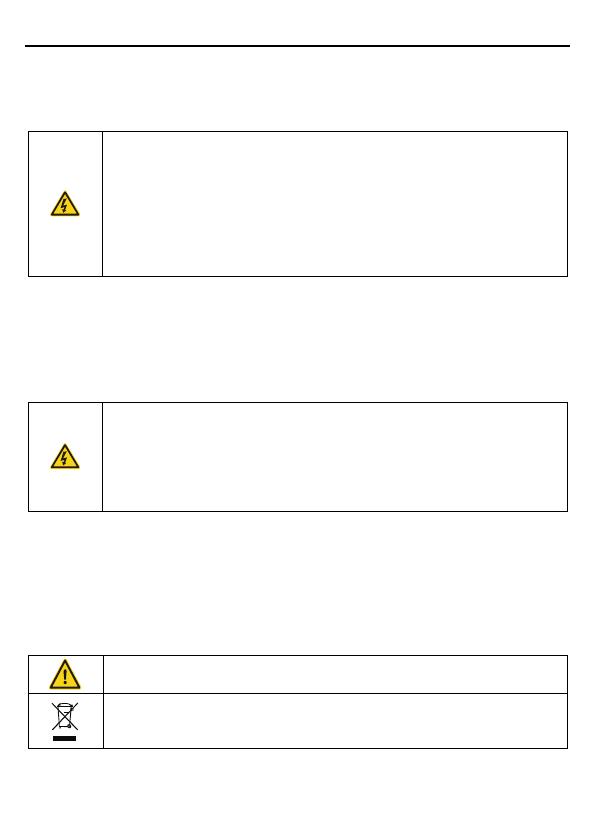
1.3.4 Scrap treatment
There are heavy metals in the VFD. Deal with it as industrial effluent.
When the life cycle ends, the product should enter the recycling system.
Dispose of it separately at an appropriate collection point instead of
placing it in the normal waste stream.
 6
7
8
9
10
11
12
13
14
15
16
17
18
19
20
21
22
23
24
25
26
27
28
29
30
31
32
33
34
35
36
37
38
39
40
41
42
43
44
45
46
47
48
49
50
51
52
53
54
55
56
57
58
59
60
61
62
63
64
65
66
67
68
69
70
71
72
73
74
75
76
77
78
79
80
81
82
83
84
85
86
87
88
89
6
7
8
9
10
11
12
13
14
15
16
17
18
19
20
21
22
23
24
25
26
27
28
29
30
31
32
33
34
35
36
37
38
39
40
41
42
43
44
45
46
47
48
49
50
51
52
53
54
55
56
57
58
59
60
61
62
63
64
65
66
67
68
69
70
71
72
73
74
75
76
77
78
79
80
81
82
83
84
85
86
87
88
89
1
/
89
100%