UserManual
OperatorLevel
Controller
APM303
Softversion:2.0.0
26/02/2016
33508000401_2_1
CALL US TODAY
1-888-POWER-58
REQUEST A QUOTE
SHOP ONLINE
www.genpowerusa.com

The"userlevel"usermanualisdesignedforuserswhoarequalifiedtosetupaninstallation
(generatingsetandenvironment).Theseusersmustbeabletomonitorthatthegeneratingsetis
operatingcorrectly(start,stop,basicsettings),tointerpretanyindications(mechanical,electrical)and
mayberequiredtocheckoneormoreparameters.
The"operatorlevel"usermanualisdesignedforthosewho–inadditiontotheskillsrequiredfor
users–havetheskillsrequiredtomodifyoneormoreparameters,tochangetheoperationofan
installation(generatingsetandenvironment).Todothis,theoperatorwillhavecompletedtraining
providedbythemanufacturerbeforehand.
The"specialistlevel"usermanualisdesignedforthosewho–inadditiontotheskillsrequiredfor
operators–havetheskillsrequiredtomakeanyspecialorcomplexmodificationtoaninstallation
(generatingsetandenvironment).Todothis,thespecialistwillhavecompletedtrainingprovidedby
themanufacturerbeforehand.
CALL US TODAY
1-888-POWER-58
REQUEST A QUOTE
SHOP ONLINE
www.genpowerusa.com

1
This document is the property of SDMO Industries.
Any communication, reproduction, publication, even partial, is forbidden, except with the written authorisation of the owner.
CONTENTS
1 Preface .................................................................................................................................................................................. 3
1.1 Safety/Operating conditions/Powering on ..................................................................................................................... 3
1.2 Integrating the APM303 in its environment .................................................................................................................... 3
1.3 Who is this manual intended for? .................................................................................................................................. 3
2 Identification of the modules .............................................................................................................................................. 4
2.1 APM303 module ............................................................................................................................................................ 4
2.2 CAN display module ...................................................................................................................................................... 4
3 Powering up the APM303 and associated configurations ................................................................................................ 4
3.1 Single generator ............................................................................................................................................................ 4
3.2 Generating set with Automatic Transfer Switch ............................................................................................................. 4
4 General description of the APM303 module ...................................................................................................................... 5
5 Selecting the operating mode ............................................................................................................................................. 5
5.1 MANU mode .................................................................................................................................................................. 5
5.2 AUTO mode .................................................................................................................................................................. 6
5.3 During operation ............................................................................................................................................................ 6
6 Display of data ..................................................................................................................................................................... 7
6.1 Main, screen 1 ............................................................................................................................................................... 7
6.2 Electrical values, screens 2 and 3 ................................................................................................................................. 7
6.3 Mechanical values, screen 4 ......................................................................................................................................... 7
6.4 Metering, screen 5 ......................................................................................................................................................... 8
6.5 Events and anomalies, screen 6 ................................................................................................................................... 8
6.6 INIT, screen 0 ................................................................................................................................................................ 8
7 Events and anomalies ......................................................................................................................................................... 9
7.1 Events ........................................................................................................................................................................... 9
7.2 Anomalies ..................................................................................................................................................................... 9
7.2.1 Appearance of an alarm ............................................................................................................................................ 9
7.2.2 Clearing an alarm ...................................................................................................................................................... 9
7.2.3 Alarm chart .............................................................................................................................................................. 10
7.2.4 Appearance of a fault .............................................................................................................................................. 10
7.2.5 Clearing a fault ........................................................................................................................................................ 10
7.2.6 Fault chart ............................................................................................................................................................... 11
7.2.7 Other anomaly displays .......................................................................................................................................... 11
8 Settings ............................................................................................................................................................................... 12
8.1 Home screen ............................................................................................................................................................... 12
8.2 Accessing settings (Main menu).................................................................................................................................. 12
8.3 Available screens ........................................................................................................................................................ 12
8.4 "Basic settings" screen ................................................................................................................................................ 13
8.5 "Engine safety features and parameters" screen ........................................................................................................ 13
8.6 "Alternator safety features" screen .............................................................................................................................. 13
8.7 "Modbus communication" screen ................................................................................................................................ 14
8.8 "Output settings" screen .............................................................................................................................................. 14
8.8.1 Selecting an output ................................................................................................................................................. 14
8.8.2 Selecting the "output code" ..................................................................................................................................... 14
8.8.3 Selecting the output action type .............................................................................................................................. 14
8.8.4 Confirming the output .............................................................................................................................................. 15
8.9 "Input settings" screen ................................................................................................................................................. 15
8.9.1 Selecting an input ................................................................................................................................................... 15
8.9.2 Selecting the "input code" ....................................................................................................................................... 15
8.9.3 Selecting the input action type ................................................................................................................................ 15
8.9.4 Confirming the input ................................................................................................................................................ 16
8.10 "Miscellaneous information" screen ............................................................................................................................. 16
8.11 Setting principle in other screens ................................................................................................................................ 16
9 Connections ....................................................................................................................................................................... 17
9.1 Rear panel connections ............................................................................................................................................... 17
9.2 K6 connector/voltage measurement ............................................................................................................................ 17
10 Technical specifications .................................................................................................................................................... 18
11 Packaging, storage and handling of the modules ........................................................................................................... 19
11.1 Packaging ................................................................................................................................................................... 19
11.2 Storage ........................................................................................................................................................................ 19
11.3 Handling ...................................................................................................................................................................... 19
11.3.1 Module packed in its box .................................................................................................................................... 19
11.3.2 Module not packed in its box .............................................................................................................................. 19
CALL US TODAY
1-888-POWER-58
REQUEST A QUOTE
SHOP ONLINE
www.genpowerusa.com

2
This document is the property of SDMO Industries.
Any communication, reproduction, publication, even partial, is forbidden, except with the written authorisation of the owner.
List of figures
Figure 1 - integration of the APM303 .............................................................................................................................................. 3
Figure 2 - front panel of the APM303 .............................................................................................................................................. 5
Figure 3 - viewing data ................................................................................................................................................................... 7
Figure 4 - main ................................................................................................................................................................................ 7
Figure 5 - current and voltage ......................................................................................................................................................... 7
Figure 6 - outputs ............................................................................................................................................................................ 7
Figure 7 - mechanical values .......................................................................................................................................................... 7
Figure 8 - meters ............................................................................................................................................................................ 8
Figure 9 - events and anomalies ..................................................................................................................................................... 8
Figure 10 - navigating through the stack .......................................................................................................................................... 8
Figure 11 - information available on screen 6 ................................................................................................................................. 8
Figure 12 - INIT ............................................................................................................................................................................... 8
Figure 13 - appearance of an alarm ................................................................................................................................................ 9
Figure 14 - appearance of a fault .................................................................................................................................................. 10
Figure 15 - an alarm displayed on the measurements screen ...................................................................................................... 11
Figure 16 - main menu .................................................................................................................................................................. 12
Figure 17 - setting principle........................................................................................................................................................... 16
Figure 18 - rear panel and connections .......................................................................................................................................... 17
Figure 19 - three phase 3P+N (4 wires) ........................................................................................................................................ 17
Figure 20 - three phase 3P (3 wires) ............................................................................................................................................ 17
Figure 21 - two phase 2P+N (3 wires) .......................................................................................................................................... 17
Figure 22 - single phase 1P+N (2 wires) ....................................................................................................................................... 17
Figure 23 - stored flat .................................................................................................................................................................... 19
Figure 24 - stored at an angle ....................................................................................................................................................... 19
Figure 25 - antistatic plastic bag ................................................................................................................................................... 19
CALL US TODAY
1-888-POWER-58
REQUEST A QUOTE
SHOP ONLINE
www.genpowerusa.com
3
This document is the property of SDMO Industries.
Any communication, reproduction, publication, even partial, is forbidden, except with the written authorisation of the owner.
1 Preface
The APM303 is a instrumentation and control system for generating sets. It enables a generating set (whether or not it is
connected to an automatic transfer switch) to be started and stopped, and manages the main safety devices for running a
generating set.
Easy navigation between the various screens enables rapid display of all the data recorded (mechanical and electrical values).
There are only three buttons associated with the generating set's PLC, making it easier to operate the generating set.
1.1 Safety/Operating conditions/Powering on
Safety
The
APM303
uses
voltage sources of different origins, which are set to potentials
dangerous to the human body. For this reason, only qualified personnel are authorised
to start up and use the APM303.
Before reading this document, we strongly recommended that you read the safety
instructions relating to starting up a generating set (see General and Safety Instructions).
SDMO Industries shall not be held responsible for failure to observe any of the instructions
described in this manual.
DANGER
Operating conditions
The conditions for use are given at the end of this manual (section ‘Technical specifications’). If a component of the equipment
must be replaced, it is necessary to pay attention to the effects of electrostatic discharges (consult the rules for handling given in
section ‘Handling’).
The APM303 has been factory configured for your application. Any change to the parameters may
alter or render unstable the behaviour of your generating set and the installation.
IMPORTANT
Powering on
Powering on is specific to the electrical equipment within which the APM303 is integrated. It is therefore necessary to consult
the wiring diagram for the equipment provided with this manual, before powering on.
1.2 Integrating the APM303 in its environment
The
APM303
is integrated into central console equipment (type S1500,
S2500, S3500, S4500), fitted on the base frame of the generating set, on
versions II and IV (enclosure).
Figure
1
-
integration of the APM303
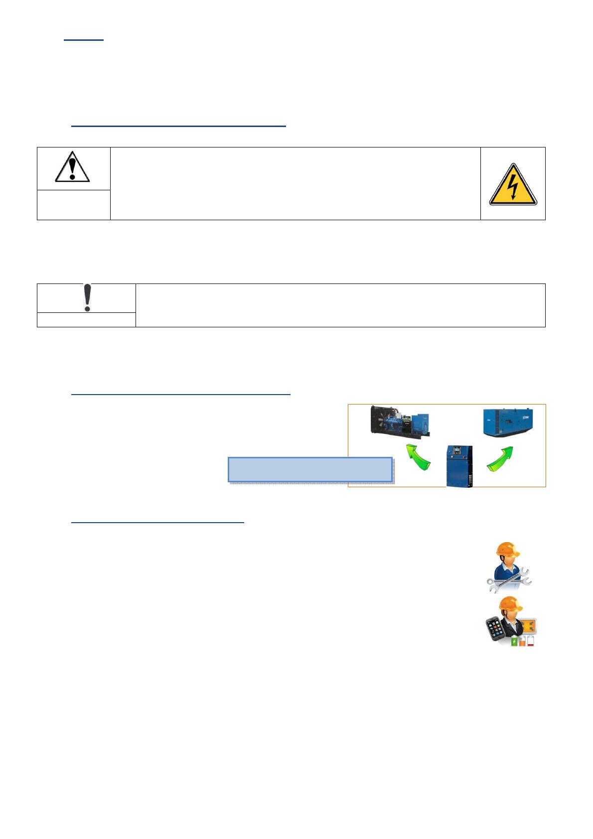
1.3 Who is this manual intended for?
This manual is intended for users and operators.
The user must be qualified to start the generating set. The user must be capable of monitoring the
generator to ensure it is running correctly, and be able to interpret the electrical and mechanical indications
provided in real time on the different screens. He or she may have to check one or more parameters.
The operator - in addition to having the skills required for users - has the skills required to modify one or
more parameters, to change the operation of an installation. To do this, the operator will have completed
training provided by SDMO Industries beforehand.
Note: for the APM303, no distinction is made between the user and the operator. This means that a user can modify all the internal parameters
(no access code in the APM303).
A self-study training aid is also available on our online Gaïa platform, however SDMO can provide any additional training required.
central consoles S1500, S2500,
S3500, S4500
CALL US TODAY
1-888-POWER-58
REQUEST A QUOTE
SHOP ONLINE
www.genpowerusa.com
 6
7
8
9
10
11
12
13
14
15
16
17
18
19
20
21
22
6
7
8
9
10
11
12
13
14
15
16
17
18
19
20
21
22
1
/
22
100%